Table of Contents
- Intro
- Working Flow
- Hardware Prototyping
- Software Design
- Testing The Software
- Hardware Design
- Parts & Links
Intro
As an electronics enthusiast, I want to make my own PCBs. I am impressed with the quality of the photoresists method. It’s really accurate if it’s done properly and the results are really nice. Photoresist PCB needs to be exposed to UV light for a certain amount of time period; that means it won’t etch well if it get overexposed or underexposed. But to begin and do the experiments with the UV light timing, we first need a UV exposure box to expose the PCBs.
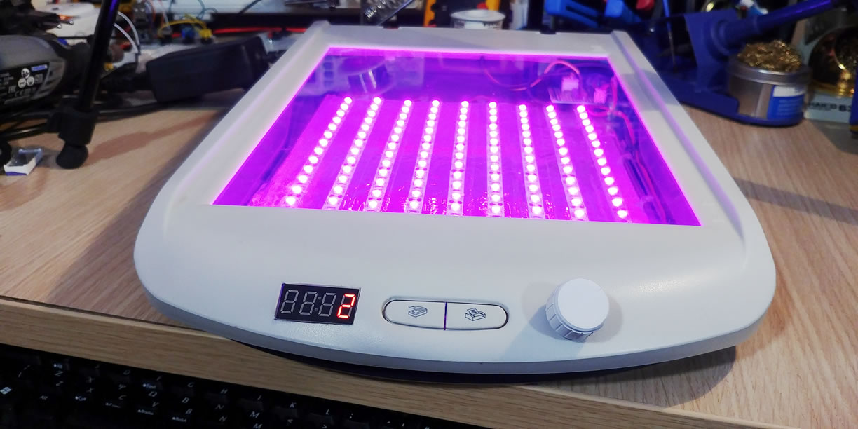
In this project we’ll use an old scanner as a box to create a PCB UV exposure box.
Working Flow
Before we begin to design our hardware and software, we first need to create the logic of our device. This will help us to decide what parts we are going to need for input and output, and then make those parts functional inside our program.
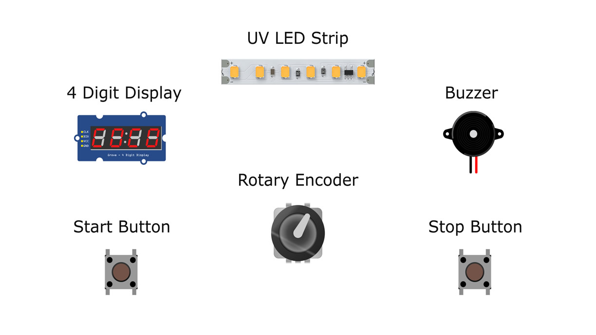 We will have to turn on and off a UV light LED strip by counting down using a timer. We need a display to set and check the time, a rotary encoder to adjust and set the time; 2 monetary buttons, one for starting and pausing the countdown timer and the LED strip and one monetary button for stopping the countdown process and turn off the LED strip.
Hardware Prototyping
We will use Arduino UNO for the prototype design on a breadboard and Arduino Nano for our final circuit. Arduino Nano is cheap and small, thus it’s suitable to use when finalizing a project.
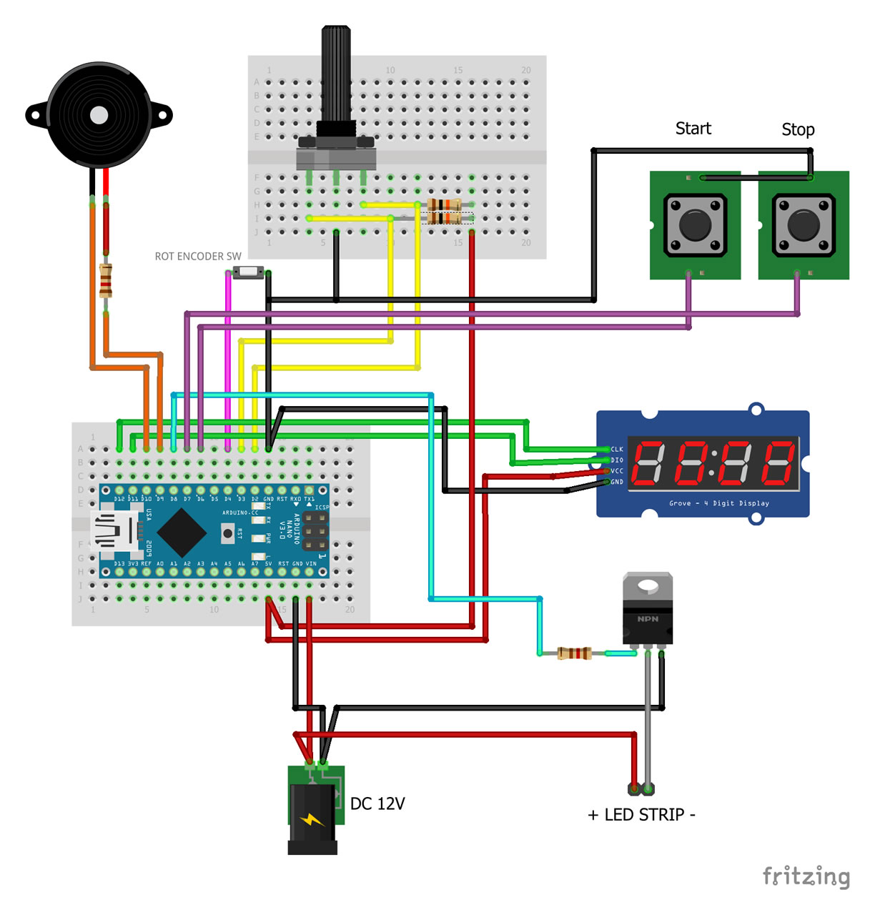
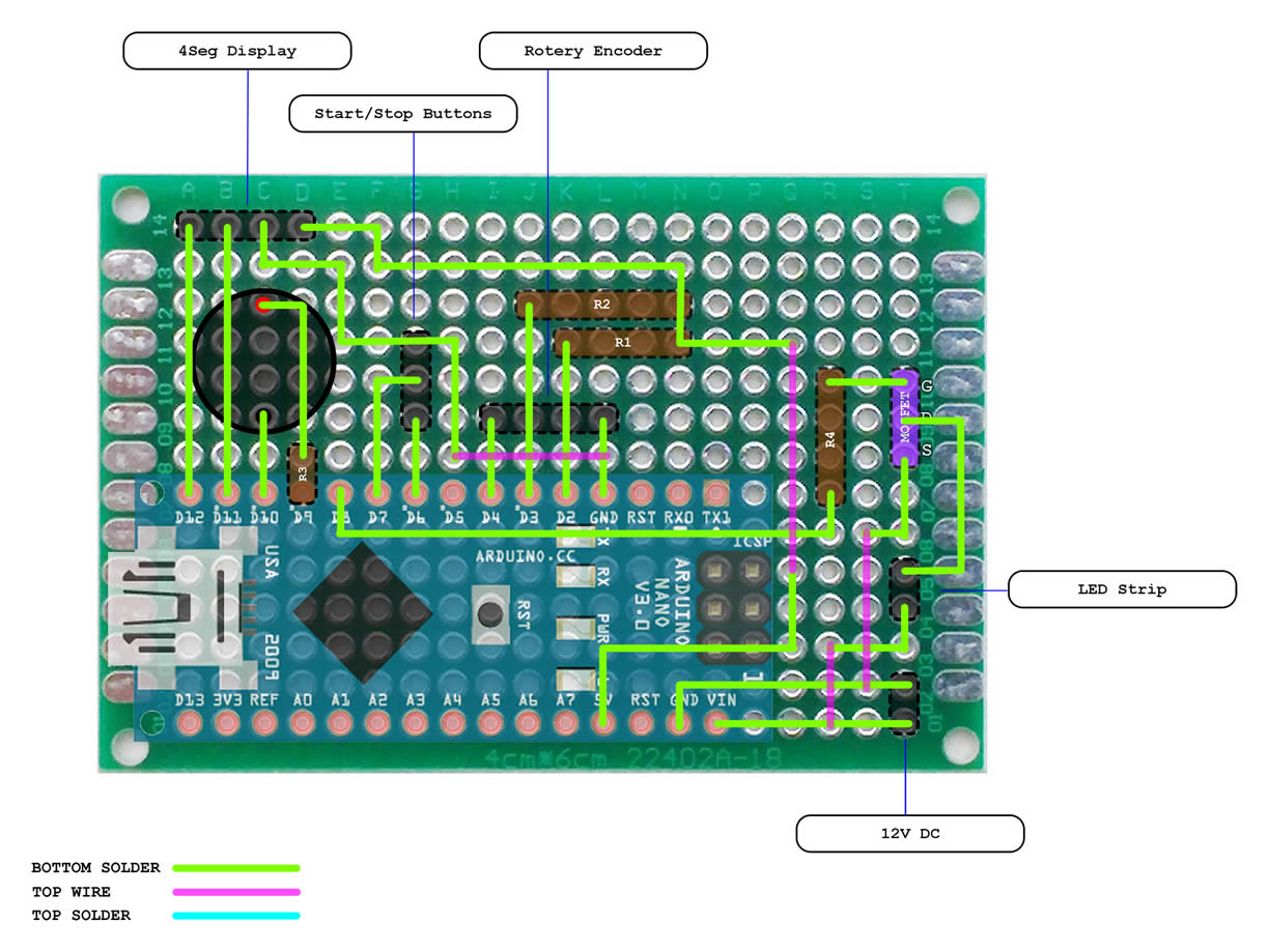
First we need to connect the rotary encoder A and B to Arduino interrupt pins D2 and D3 and connect each wire to Arduino positive five volts (+5V) through a 10K resistor;
We will use the rotary encoder monetary switch, so we’re connecting it to pin D4 and Ground;
We connect the 4 digit display Clock to D12 pin, Data to D11 pin and of course positive 5 volts (+5V) and Ground;
We connect the start button to pin D6 and the stop button to pin D7.
We connect the buzzer to pins D9 and D10 using a one 120Ω resistor and finally for the MOSFET we connect the gate to pin D8 using a 120Ω resistor, the drain to the LED strip negative (-), the source to the ground and the LED strip positive (+) to our 12V power source.
Of course we will power the Arduino from the same 12V power supply.
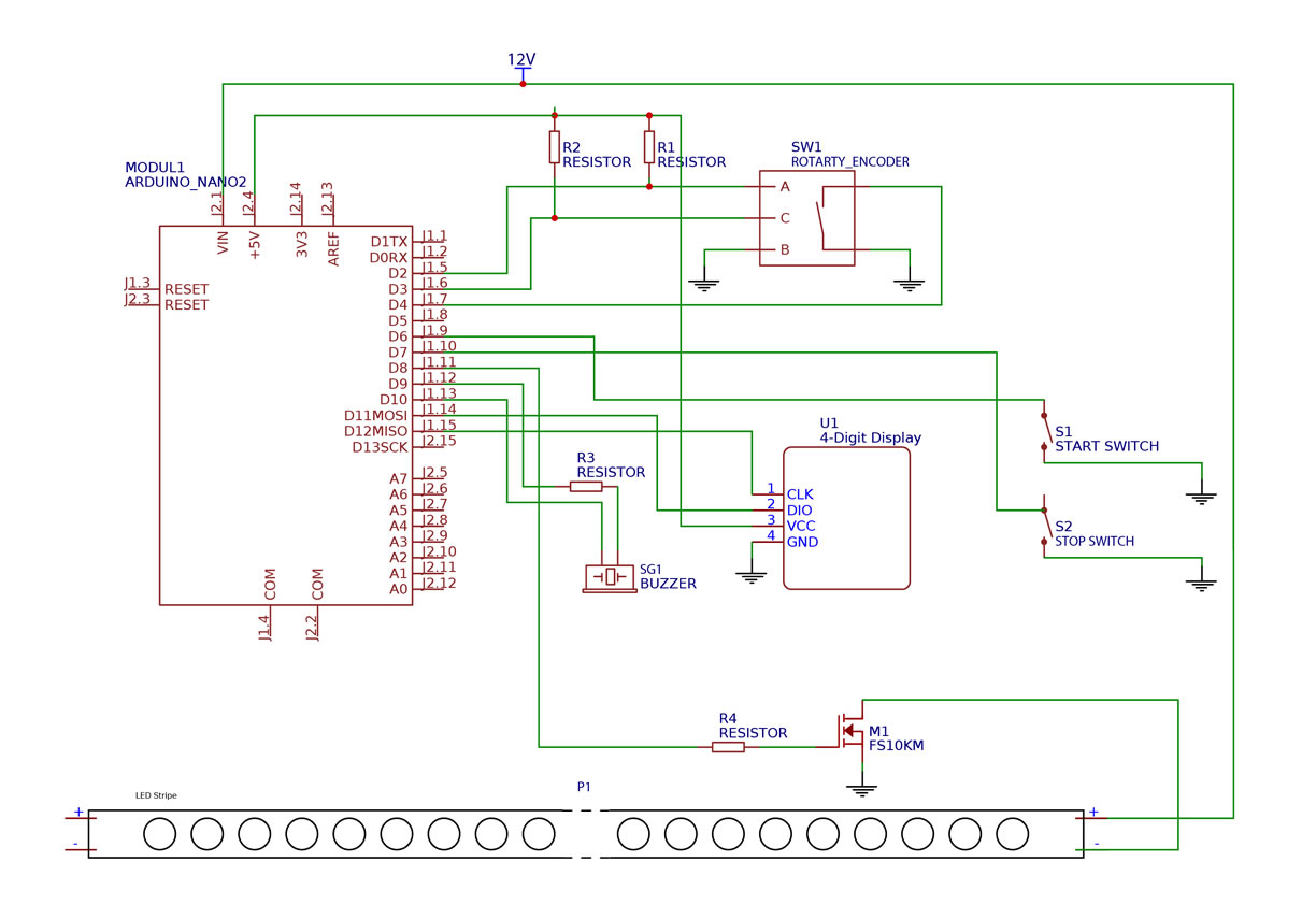
We connect everything using a breadboard and according to the breadboard diagram or the schematic, and now we are ready to begin and create our software
Software Design
 As a professional software engineer, I like to write clean and structured code, and since Arduino has a C++ compiler, I am going to use classes and multiple files to define the constants, variables and program classes. I’m using Eclipse IDE to write and compile my Arduino projects. It has a functions and class members list which is very handy when writing complex code.
It’s always nice to first design and create work flows for our programs.
As a professional software engineer, I like to write clean and structured code, and since Arduino has a C++ compiler, I am going to use classes and multiple files to define the constants, variables and program classes. I’m using Eclipse IDE to write and compile my Arduino projects. It has a functions and class members list which is very handy when writing complex code.
It’s always nice to first design and create work flows for our programs.
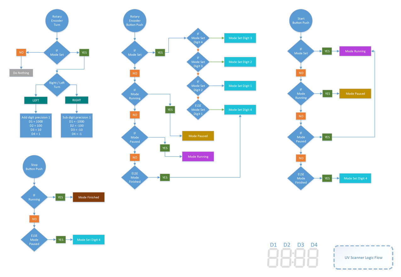
Modes
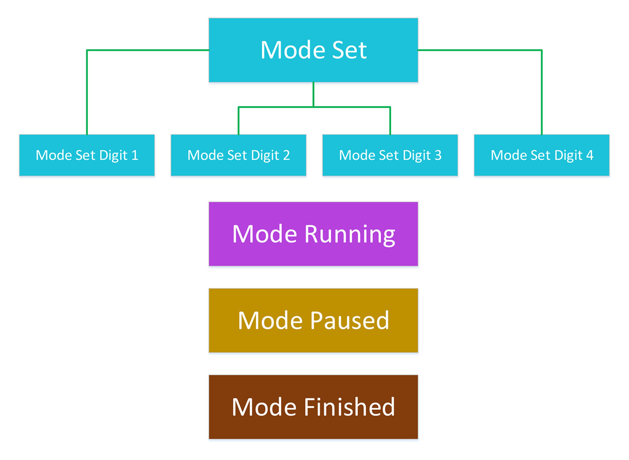 We begin with the operation modes; first we have the set mode which sets the timer seconds and it has four sub-modes, one to set each digit.
Next we have the running mode, which turns the LED strip on and starts the timer countdown.
Then we have the paused mode, which the LED strip turns off, the countdown pauses and it’s ready to continue from where it was paused.
And finally, we have the finished mode, which of course the LED strip turns off and the timer resets to the set value.
We begin with the operation modes; first we have the set mode which sets the timer seconds and it has four sub-modes, one to set each digit.
Next we have the running mode, which turns the LED strip on and starts the timer countdown.
Then we have the paused mode, which the LED strip turns off, the countdown pauses and it’s ready to continue from where it was paused.
And finally, we have the finished mode, which of course the LED strip turns off and the timer resets to the set value.
Rotary Encoder Rotation
The rotary encoder rotation works only when the program is at set mode. When it turns left, it adds thousands for the digit 1, hundreds for the digit 2, tenths for digit 3 and ones for the last digit 4. It subtracts the same values for each digit when it turns at the opposite side.
Rotary Encoder Button Push
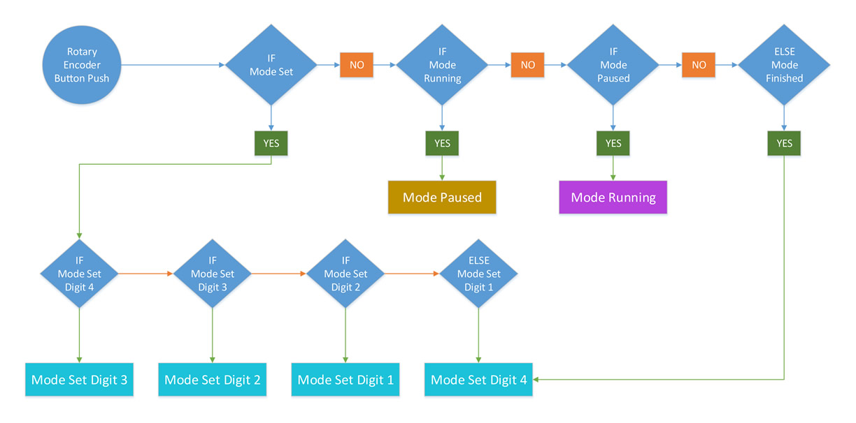
When the rotary encoder button is pushed, it loops through the set sub-modes for each digit if the program is at set mode. If it’s in running mode, it goes to pause mode; if it’s in paused mode it goes to running mode. And finally if it’s in finished mode, it goes in set mode at digit 4.
Start Button Push
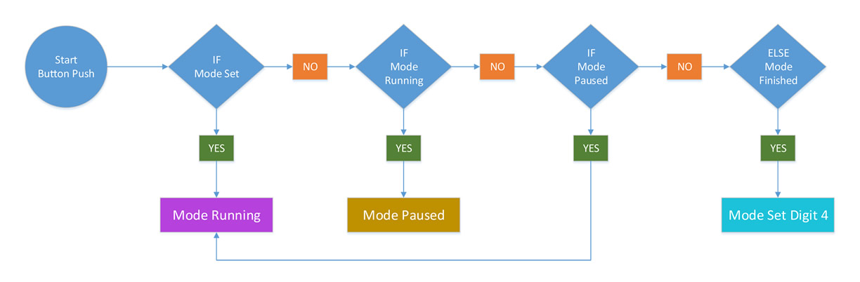
When the start button is pushed and the program is in set mode, the program goes at running mode. If it’s in running mode, it pauses and if it’s in finished mode it goes to set mode at digit 4.
Stop Button Push
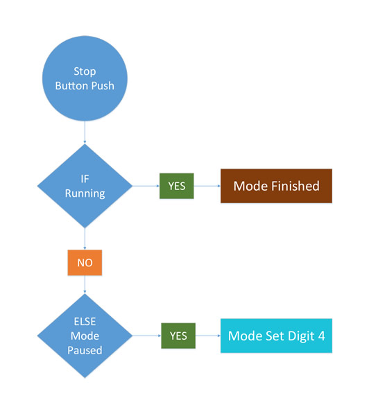
And finally the stop button push, if it’s in running mode then it goes to finished mode, else if it’s in paused mode it goes to set mode at digit 4.
Testing The Software
After we implement all that logic and write our code, it’s finally time to test and see if it’s working as expected.
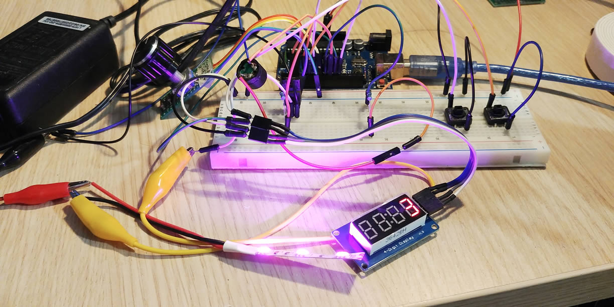
We try and turn the rotary encoder to test the set mode. We go through each digit, to see if all the set logic works as expected. Then we push the start button to test the running mode, we push it again to test the pause mode; we wait to check if the finished mode is working; and finally we check the stop button functionality. When we are done and make sure everything is working as in our designs, we continue to the final hardware implementation.
Hardware Design
We collect all the components that will be used for the final device.
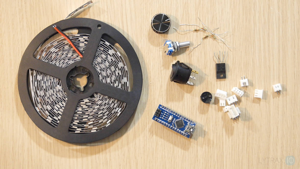
I am using a proto board to solder the Arduino Nano and all the components. It’s nice to design the proto-board layout first and then we will solder all the components and the connections according to our design.
After we’re done soldering all the components on the proto board, we are now ready to test if the proto board is working properly. It’s now time for the scanner box modifications. The scanner I’m using has two monetary switches in the front, which of course I’m going to use as start and stop buttons. At the back, the scanner has a USB port and a DC power jack. I will use both ports, the USB port to connect the Arduino in case I need to update the software without opening the box and the DC power jack to power the whole device using the scanners transformer.
I begin by taking apart and removing all the components inside the scanner. Then I use aluminum foil to cover the exposed area just for the light to reflect. We need to cover the aluminum foil with some kind of transparent tape, just to minimize the risk of sorting any strip connections.
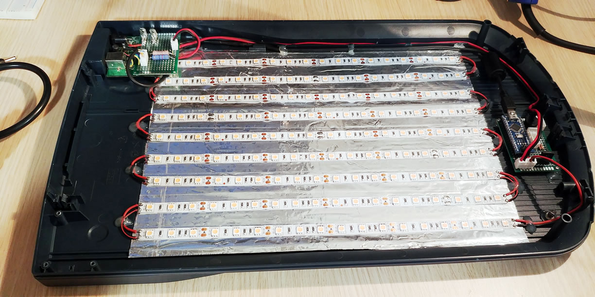
We measure the exposure area and we cut the LED strip in smaller pieces. We solder the led strip pieces together. We need to be very careful and don’t make any mistakes here. I did a mistake and I had to unsolder and resolder almost all the strip pieces! We test all the LED pieces and then we stick the LED strips on the insolated aluminum foil. I’m drilling an 8mm hole for the rotary encoder and cutting enough plastic just to fit the 4 digit display.
I’m cutting and using the scanner board because it already has a USB and a DC power jack connectors.

A power switch with an LED will be attached at the back rear. I will create a small board to connect the USB, power jack, power switch and send all the cables to the main board at the front of the box.
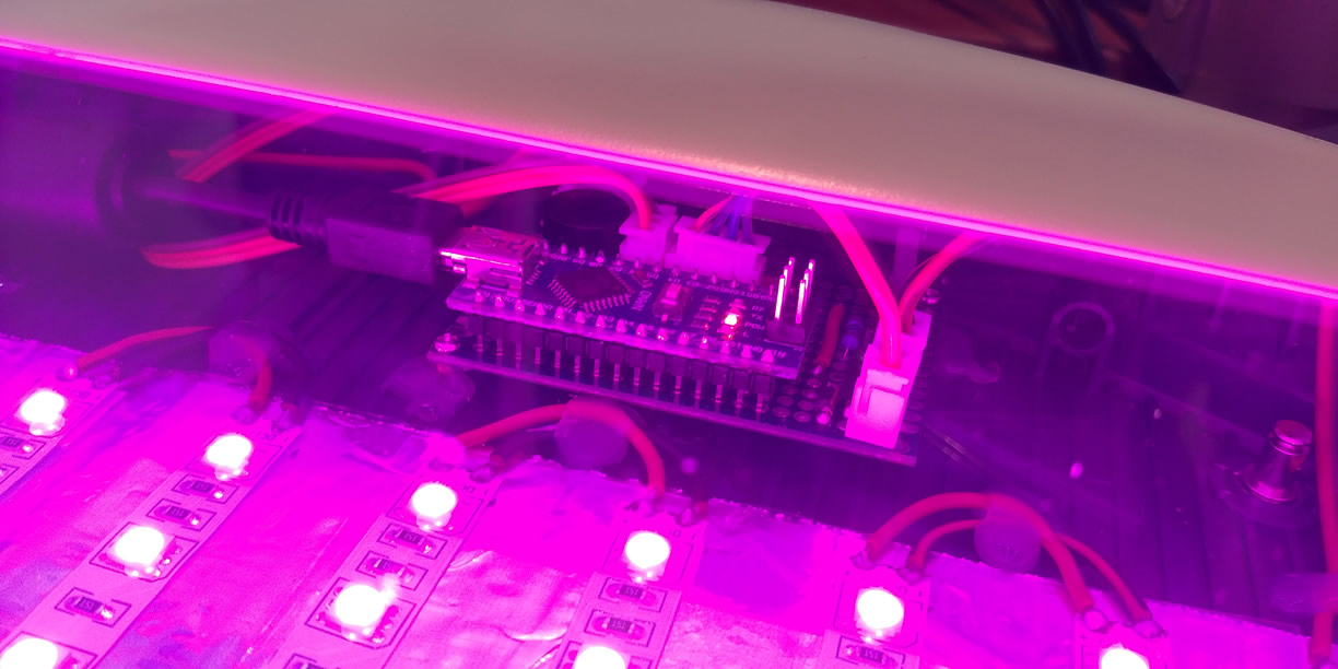
We attach and hot glue all the components; we connect all the connectors and finally we are testing the device to see if everything is working properly.
Parts & Links
Parts List
- R1: 10K
- R2: 10K
- R3: 120
- R4: 120
- MOSFET: FS10KM-10 (N-Channel)
- Rotary encoder with a monetary switch
- Monetary switch X 2
- 4 digit LED display module
- UV LED Strip
Source Code & Design Assets
Project on Github: clytras/CL_UVScanner